Parallel-Split Shadow Mapping
The parallel-split shadow maps allow each map to sample a smaller area by increasing the sampling frequency in texture space. This technique requires how to determine the split positions when splitting the view frustum. In this project, scene-independent proejction is only considered.
Algorithm
Let be the number of split, then the view frustum is split into and the clip plane is into . Especially, (near plane position of the main camera) and (far plane position of the main camera). The overview of this algorithm is as follows:
- calculate each and split the view frustum into parts.
- for each , calculate the special crop matrix using the view-projection matrix of the light.
- generate the depth map from the light view using the crop matrix.
- render the scene by the depth range of .
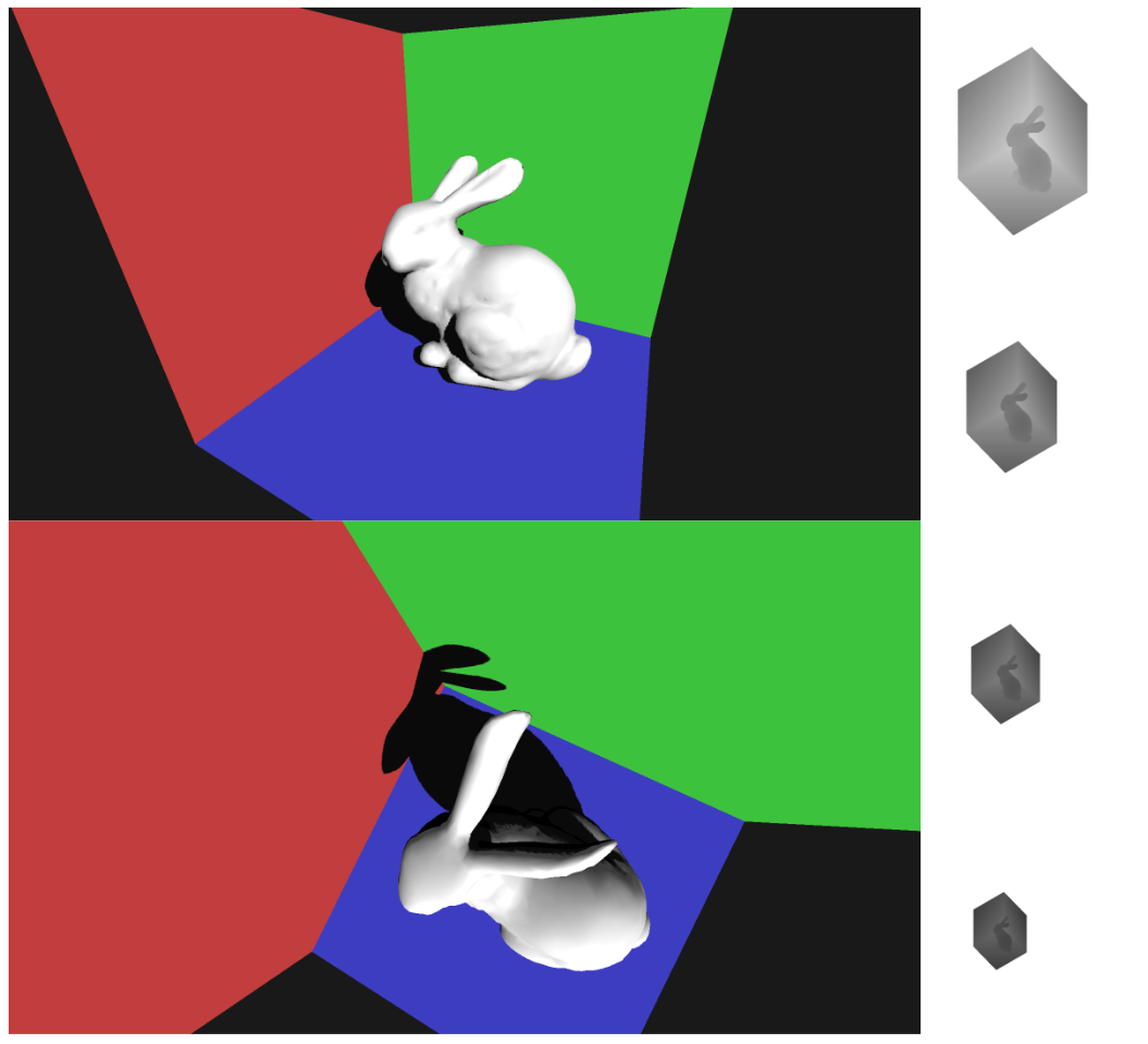
step 1: calculate each and split the view frustum into parts.
Note that the range of the normalized shadow plane is [-1, 1] not [0, 1]. NDC ranges from -1.0 to 1.0 in OpenGL system.
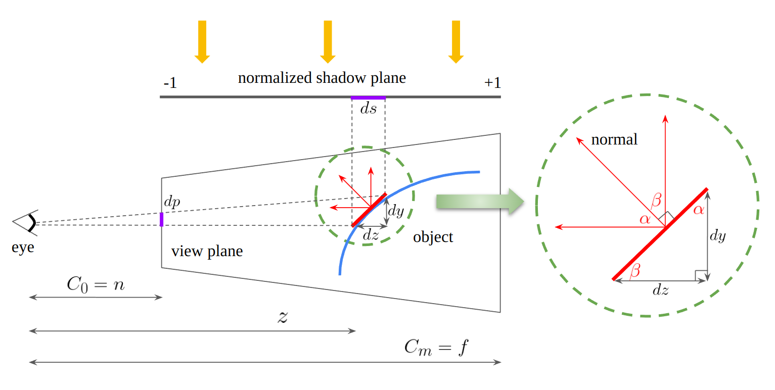
To determine the proper split positions, consider the shadow map aliasing error which is divided into perspective aliasing and projection aliasing. The above figure shows that the small red edge on an object is projected on the view plane and normalized shadow plane. Let the length of this red edge be . Then,
By triangle similarity, the shadow map aliasing error can be written as follows:
In this situation, perspective aliasing happens when is large and projection aliasing when is large. Projection aliasing occurs usually for sufaces almost parallel to the light direction, which means is close to and is almost zero. So this aliasing depends on local geometry details and requires an expensive scene analysis to reduce errors. Perspective aliasing, on the other hand, is caused by the viewer’s perspective projection matrix, which means that this aliasing can be imporved using a perspective projection transformation. Theoretically the optimal distribution of perspective aliasing makes the error constant over the entire depth range. So let this aliasing be a constant .
Considering when , the constant can be calculated.
For finding the -th clip plane position , as the resolution allocated for each split should be of the overall texture resolution.
This is called the logarithmic split scheme. Without this, the uniform split scheme can be used to find .
However, [1] suggests that the weighted combined version of logarithmic and uniform split schemes. So these two values can be mixed with linear interpolation.
step 2: for each , calculate the special crop matrix using the view-projection matrix of the light.
Once the view frustum is split, all the vertices for each are transformed to NDC using the view-projection matrix of the light. Note that the minimum -value among the transformed vertices is set to be so that the near plane position remains unchanged. After that, the crop matrix is calculated to effectively zoom-in the light’s frucstum. Note that a matrix is stored in column-major to send to OpenGL.
Note that the range of the normalized shadow plane is [-1, 1] not [0, 1]. NDC ranges from -1.0 to 1.0 in OpenGL system.
  glm::mat4 crop(1.0f);
  crop[0][0] = 2.0f / (max_point.x - min_point.x);
  crop[1][1] = 2.0f / (max_point.y - min_point.y);
  crop[2][2] = 2.0f / (max_point.z - min_point.z);
  crop[3][0] = -0.5f * (max_point.x + min_point.x) * crop[0][0];
  crop[3][1] = -0.5f * (max_point.y + min_point.y) * crop[1][1];
  crop[3][2] = -0.5f * (max_point.z + min_point.z) * crop[2][2];
step 3: generate the depth map from the light view using the crop matrix.

At first, generate the depth map from the light view. In this situation, the crop matrix should be multiplied after the projection matrix of the light.
step 4: render the scene by the depth range of .
With the depth map from step 3, the scene can be rendered finally. However, for each , the depth range should be adjusted considering and near/far plane positions.
References
[1] Chapter 10. Parallel-Split Shadow Maps on Programmable GPUs
[2] Wimmer, Michael et al. “Light Space Perspective Shadow Maps.” Rendering Techniques (2004).