OpenGL Pipeline
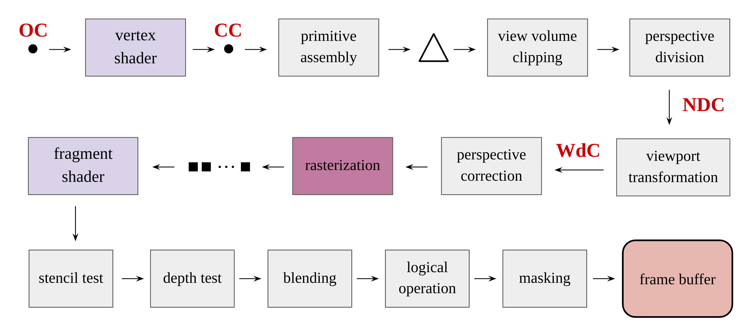
This is an overview of OpenGL fixed-function pipeline with shaders. Some routines are missing, but the main features are summarized.
Object Coordinates(OC)
OC is usually space for designers who create object polygonal models. Sometimes, these coordinates can be omitted, and World Coordinates(WC) can be directly used from the beginning.
Vertex Shader & Clip Coordinates(CC)
Per-vertex operation is processed in a vertex shader. Each vertex in the object is usually transformed to Eye Coordinates(EC) by the view matrix. Thereafter, each vertex is multiplied by the projection matrix again to send it to CC.
Primitive Assembly
In CC, vertices are assembled into the desired primitives. The primitive can be any shape OpenGL supports set by the programmer with a draw call. Although the primitive can be a point or a line, the most commonly used primitive is a triangle.
View Volume Clipping
If the primitives lie out of the view frustum, they can be removed before going further. When the whole primitive is out of the frustum, it is all thrown away. However, if the part of the primitive is out, the primitive is clipped to be within the frustum.
Perspective Division
The projection matrix that is used in a vertex shader is a matrix so that vertices can be transformed to Normalized Device Coordinates(NDC). Even though this projection matrix makes vertices lie in CC, not NDC, this is because of the non-linear property of the perspective projection. As such, each vertex must be divided by its w-component to go to NDC. This division gives perspective to the scene. Even with orthogonal projection used, not perspective projection, this division is still valid because the w-component is 1 in this case. Note that NDC is implicitly left-handed coordinates while OpenGL system is right-handed system.
Viewport Transformation
As the last transformation, the viewport matrix transforms the primitives in NDC to Window Coordinates(WdC). This space is for the screen the programmer set. That is, the primitives are now located where they should be rendered.
Perspective Correction & Rasterization
Since the scene has non-linearity in WdC, attributes of each vertex cannot be linearly interpolated for per-fragment operations later. To resolve this issue, attributes can be interpolated by perspective correction, which is considering this non-linearity not by the classic linear interpolation. That is, the perspective correction is processed from the point of view of EC or OC which has linearity. Thus, the primitives can be now fragmented through rasterization.
Fragment Shader & Per-Sample Operations
After rasterization, the fragment shader can process these fragments to calculate lighting or other desired per-fragment operations. After the fragment data output from the fragment shader, they are passed through a sequence of steps. These steps include pixel ownership test, scissor test, alpha test, stencil test, and depth test. All these tests can be activated only when they are enabled. Stencil and depth tests are commonly used ones and it is important to remember that stencil test precedes depth test. After these steps, color blending and logical operations happen, which are performed between the fragment colors and framebuffer colors. Lastly, the masking operation can allow the programmer to prevent color, depth, and stencil writes.