Branch Divergence
SIMT Stack
How does GPU hardware enable threads within a warp to follow different paths through the code? One approach used in current GPUs is to serialize the execution of threads following different paths within a given warp. To achieve this serialization of divergent code paths, one approach is to use a stack. Each entry on this stack contains three entries: a reconvergence program counter (RPC), the address of the next instruction to execute (Next PC), and an active mask.
do {
    t1 = tid * N;         // A
    t2 = t1 + i;
    t3 = data1[t2];
    t4 = 0;
    if (t3 != t4) {
        t5 = data2[t2];   // B
        if (t5 != t4) {
            x += 1;       // C
        }
        else {
            y += 2;       // D
        }
    }
    else {
        z += 3;           // F
    }
    i++;                  // G
} while (i < N);
A:    mul.lo.u32      t1, tid, N;
      add.u32         t2, t1, i;
      ld.global.u32   t3, [t2];
      mov.u32         t4, 0;
      setp.eq.u32     p1, t3, t4;
@p1   bra             F;
B:    ld.global.u32   t5, [t2];
      setp.eq.u32     p2, t5, t4;
@p2   bra             D;
C:    add.u32         x, x, 1;
      bra             E;
D:    add.u32         y, y, 2;
E:    bra             G;
F:    add.u32         z, z, 3;
G:    add.u32         i, i, 1;
      setp.le.u32     p3, i, N;
@p3   bra             A;
The above codes illustrate CUDA C code that contains two branches nested within a do-while loop, and the corresponding PTX assembly. Note that Basic Block E appears only in the PTX assembly.
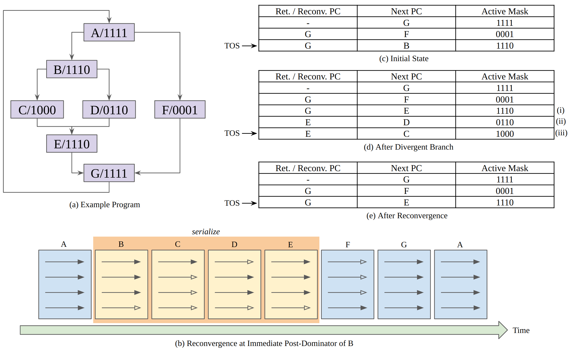
Figure (a) illustrates a control flow graph (CFG) corresponding to this code. As indicated by the label “A/1111” inside the top node of the CFG, initially all four threads in the warp are executing the code in Basic Block A. Note that one warp has only four threads to help explain conveniently. These four threads follow different (divergent) control flow after executing the branch. Specifically, as indicated by the label “B/1110”, the first three threads fall through to Basic Block B. Since three threads branch to Basic Block B and one thread branches to Basic Block F, two new entries have been added to the top of the stack (TOS). The next instruction that the warp executes is determined using the Next PC value in the TOS entry. In Figure (c), this Next PC value is B, which represents the address for the first instruction in Basic Block B. The corresponding Active Mask entry, “1110”, indicates only the first three threads in the warp should execute this instruction.
The first three threads in the warp continue executing instructions from Basic Block B until they reach the nested branch. This branch divergence causes three changes to the stack. First, the Next PC entry of the TOS entry prior to executing the branch, labeled (i) in Figure (d), is modified to the reconvergence point of the branch, which is the address of the first instruction in Basic Block E. Then, two entries, labeled (ii) and (iii) in Figure (d), are added, one for each of the paths followed by threads in the warp after executing the branch.
An interesting question is “what order should be used to add the entries to the stack following a divergent branch?” To reduce the maximum depth of the reconvergence stack to be logarithmic in the number of threads in a warp, it is best to put the entry with the most active threads on the stack first and then the entry with fewer active threads. Figure (d) follows this order while Figure (c) uses the opposite order.
To sum up, the SIMT stack helps efficiently handle two key issues that occur when all threads can execute independently. The first is nested control flow. In nested control flow, one branch is control dependent upon another. The second issue is skipping computation entirely while all threads in a warp avoid a control flow path. For complex control flow this can represent a significant savings. Traditionally, CPUs supporting predication have handled nested control flow by using multiple predicate registers. In GPU, however, hardware overhead increases exponentially as the number of threads grows if predicate registers are used. So, the SIMT stack can reduce this overhead.
SIMT Deadlock
The stack-based implementation of SIMT can lead to a deadlock condition called SIMT deadlock. In the code below, line A initializes the shared variable, mutex, to zero to indicate that a lock is free. On line B, each thread in a warp executes the atomicCAS operation, which performs a compare-and-swap operation on the memory location containing mutex. Importantly, the compare-and-swap performs the sequence of logical operations atomically for each thread. Thus, multiple accesses by atomicCAS to any single location, made by different threads within the same warp, are serialized.
*mutex = 0;                         // line A
while (!atomicCAS( mutex, 0, 1 ));  // line B
// critical section                 // line C
atomicExch( mutex, 0 );
As all threads access the same memory location, only one thread will see the value of mutex as 0, and the remaining threads will see the value as 1. Next, while keeping the SIMT stack in mind, consider what happens with the while loop on line B after atomicCAS returns. Different threads see different loop conditions. Specifically, one thread will want to exit the loop while the remaining threads will want to stay in the loop. The thread that exits the loop will have reached the reconvergence point and thus will no longer be active on the SIMT stack and thus unable to execute the atomicExch operation to release the lock on line C. The threads that remain in the loop will be active at the top of the SIMT stack and will spin indefinitely. The resulting circular dependence between threads introduces a new form of deadlock, called SIMT deadlock.
Stackless SIMT
Since Volta architecture, NVIDIA introduced their new thread divergence management approach, called Independent Thread Scheduling, to avoid SIMT deadlock. The key idea is to replace the stack with per warp convergence barriers. In contrast to a stack-based SIMT implementation, with a convergence barrier implementation, the scheduler is free to switch between groups of diverged threads. This enables forward progress between threads in a warp when some threads have acquired a lock while others have not.
Reference
[1] Tor M. Aamodt, Wilson Wai Lun Fung, and Timothy G. Rogers. 2018. General-purpose Graphics Processor Architectures. Morgan & Claypool Publishers.